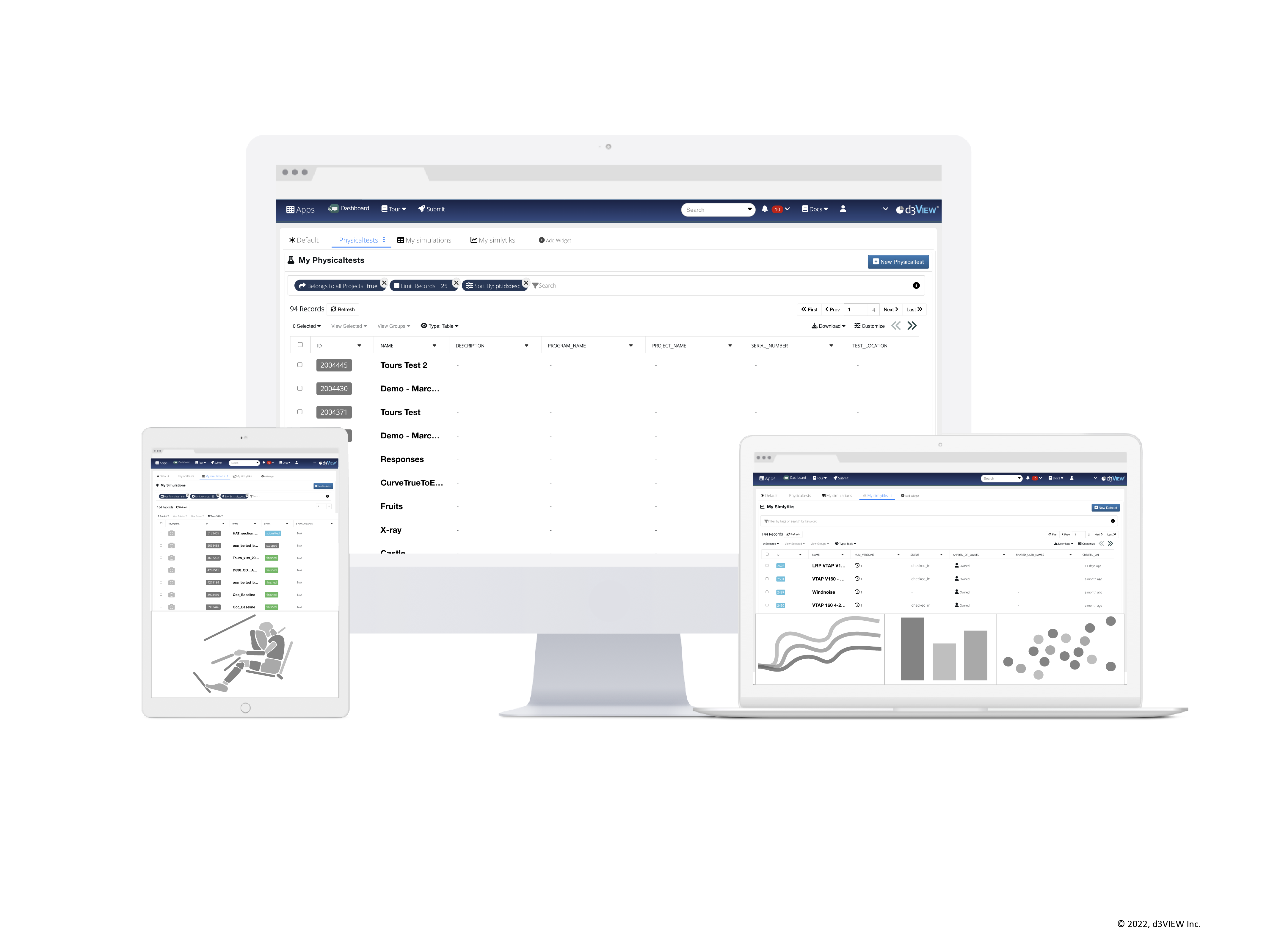
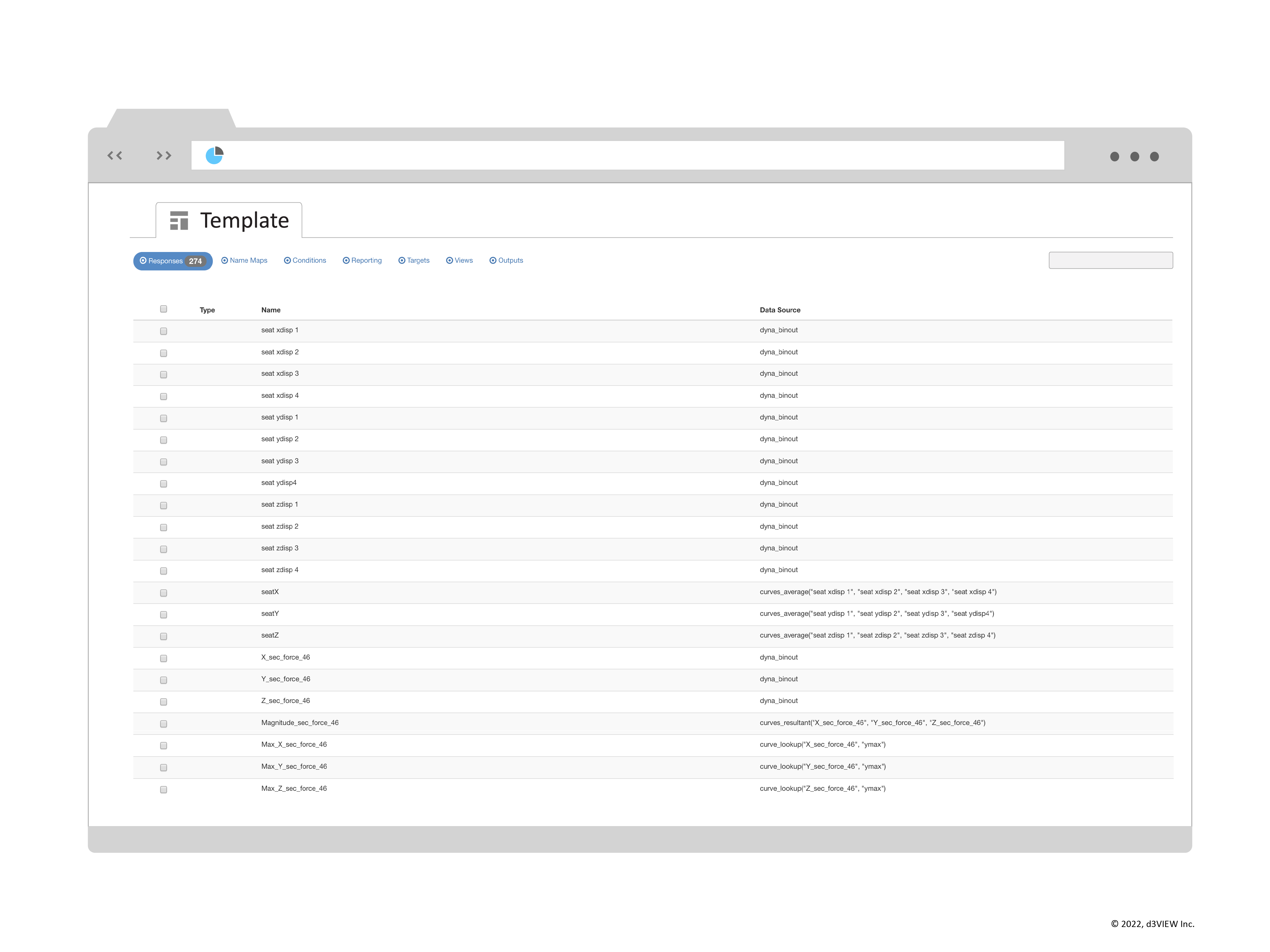
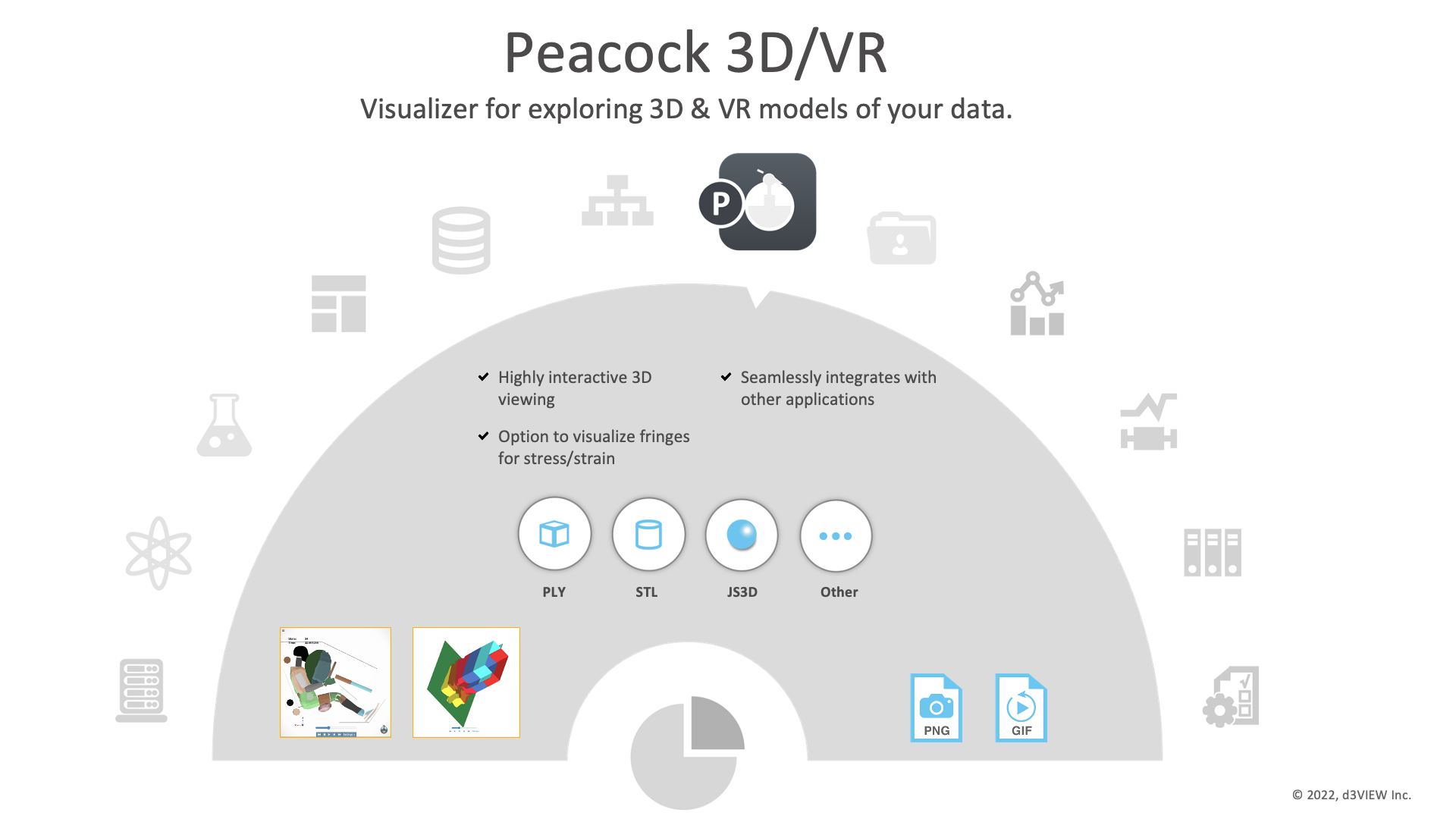
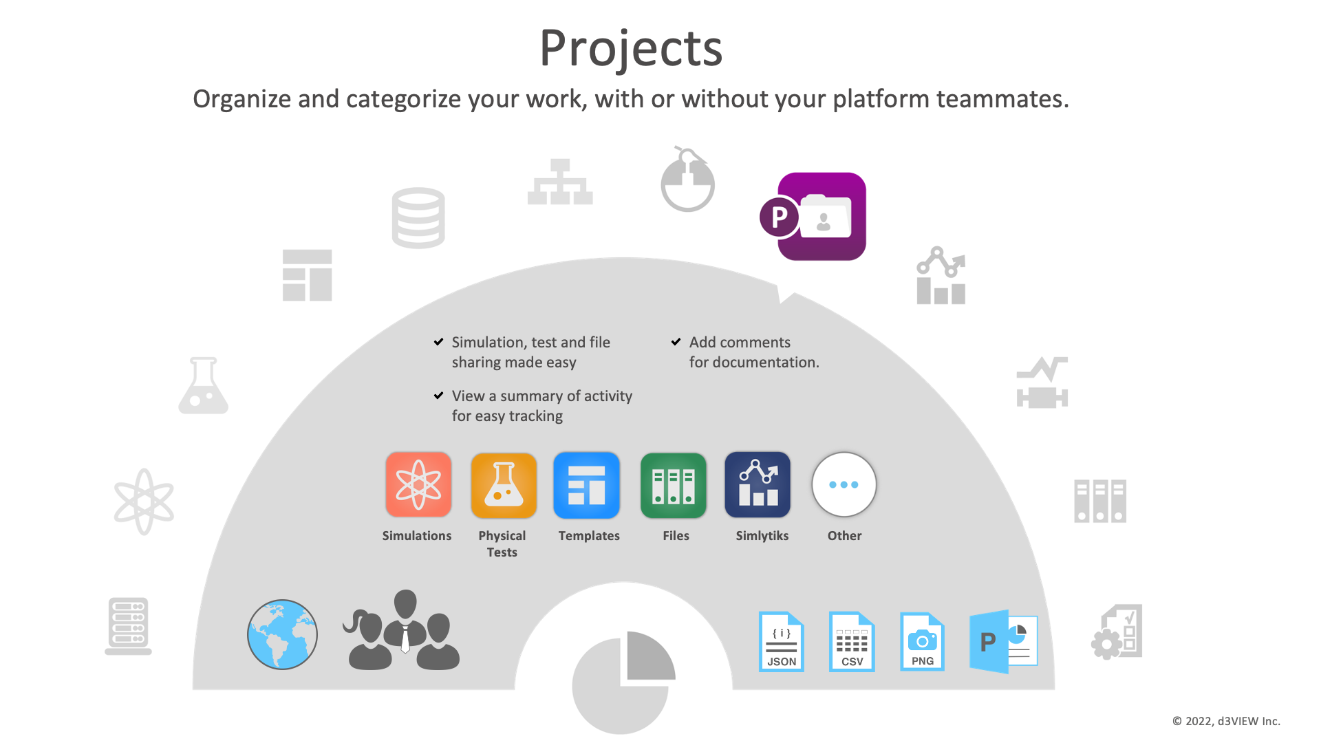
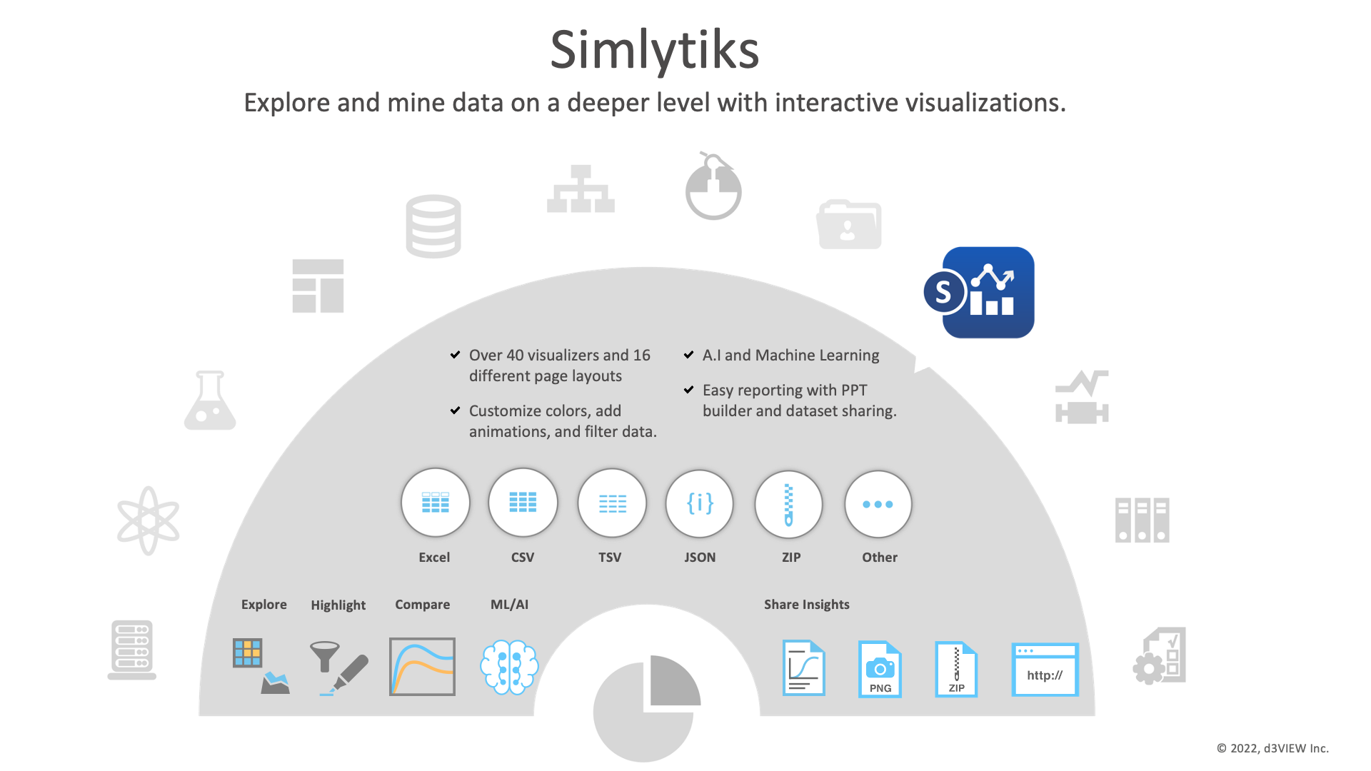
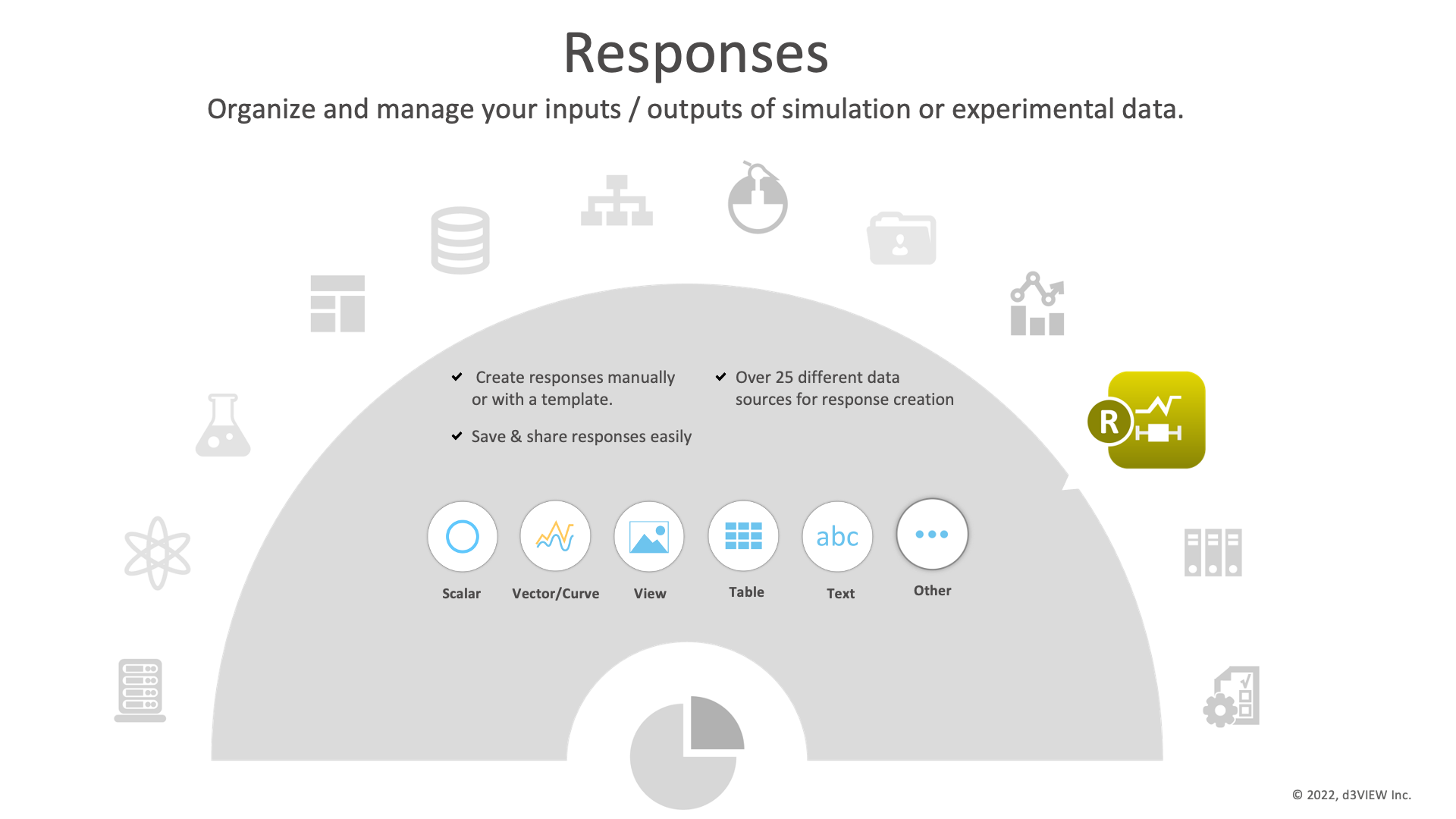
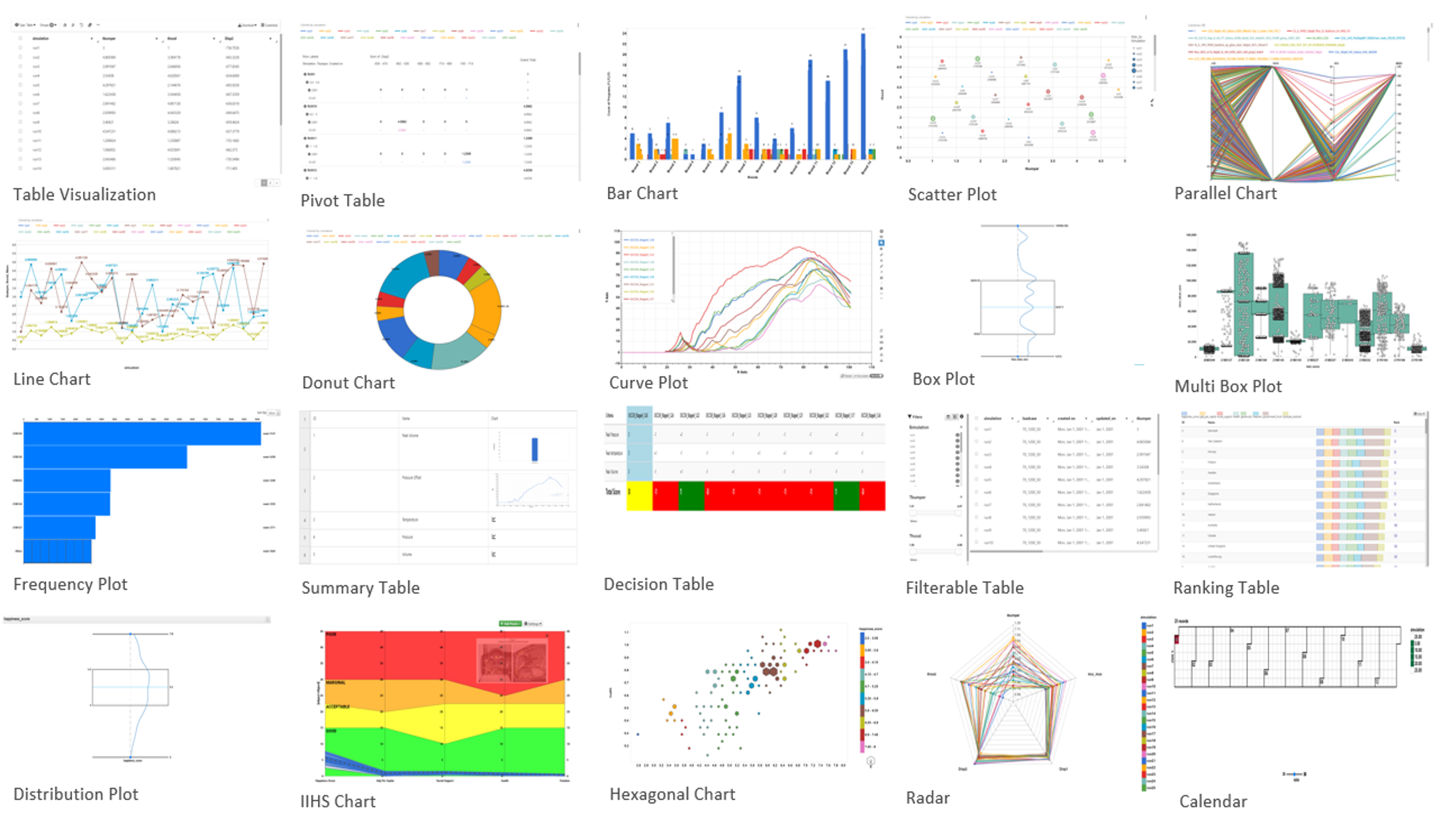
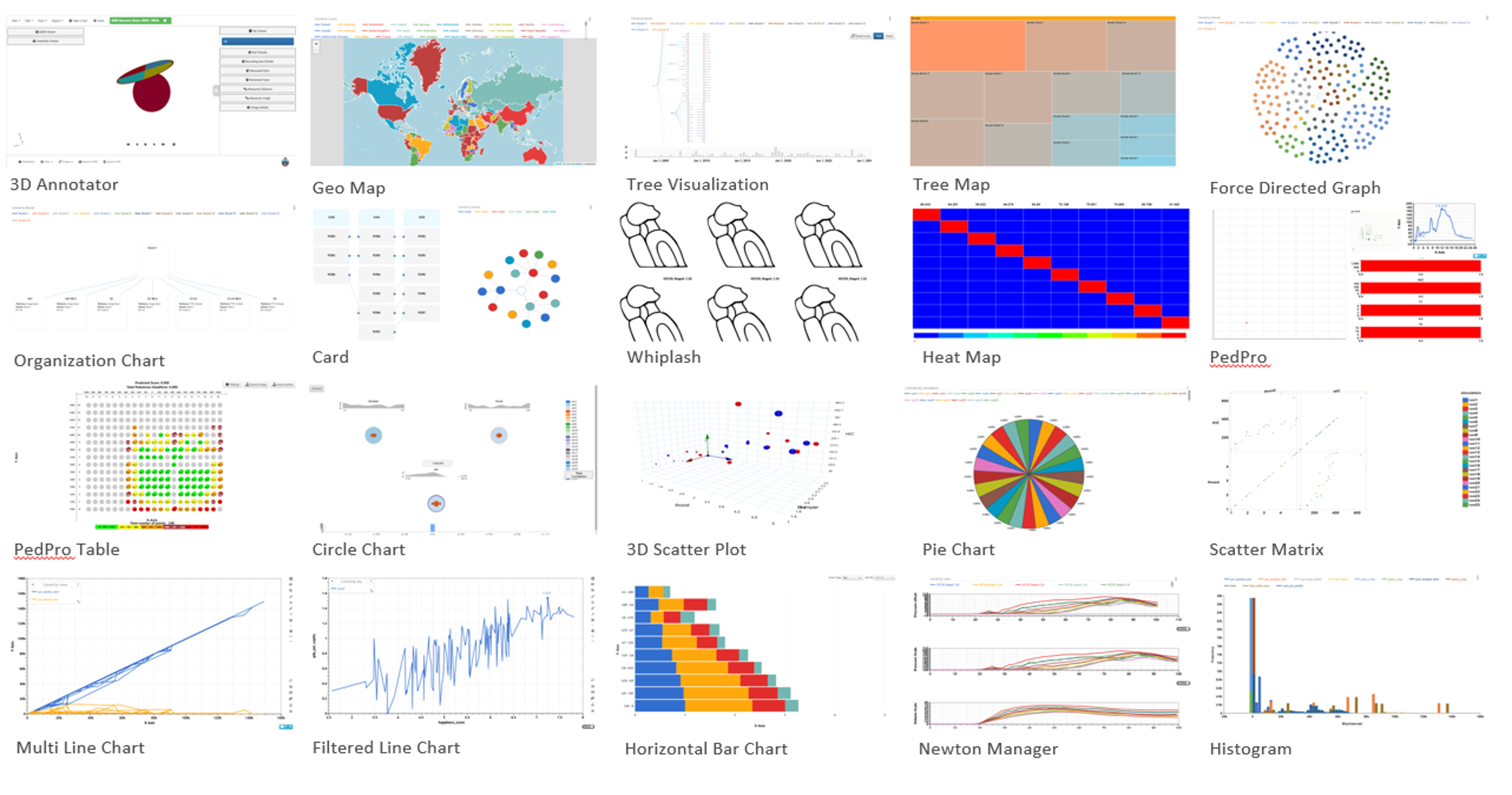
d3VIEW provides rich library of data-driven visualizers to explore and gain insights from data.
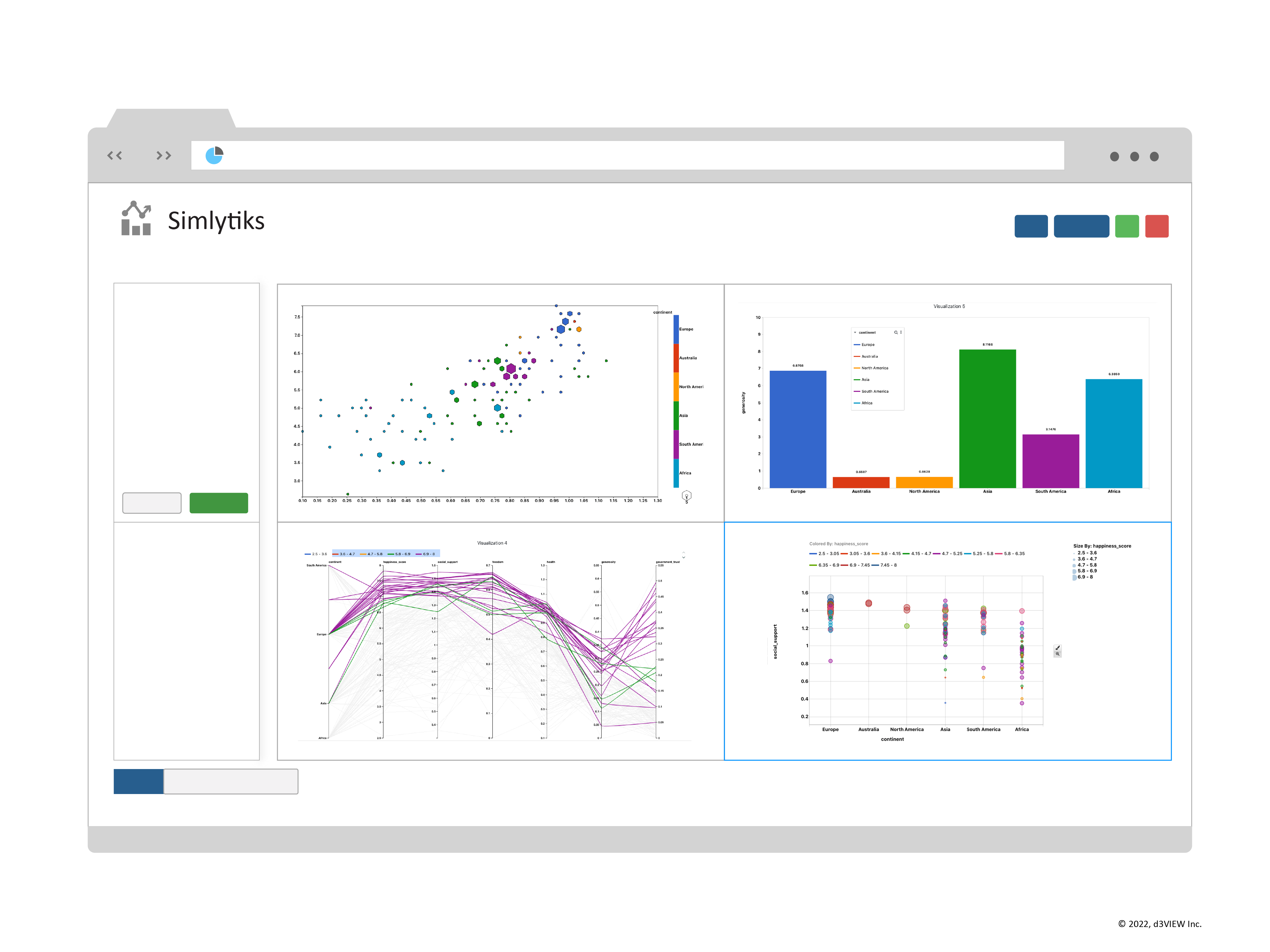
Visualizers are data-driven, which means every aspect of the data such as the line thickness, line width, line color are driven by data. This allows data to be presented in a variety of different ways associated with data to uncover hidden information.
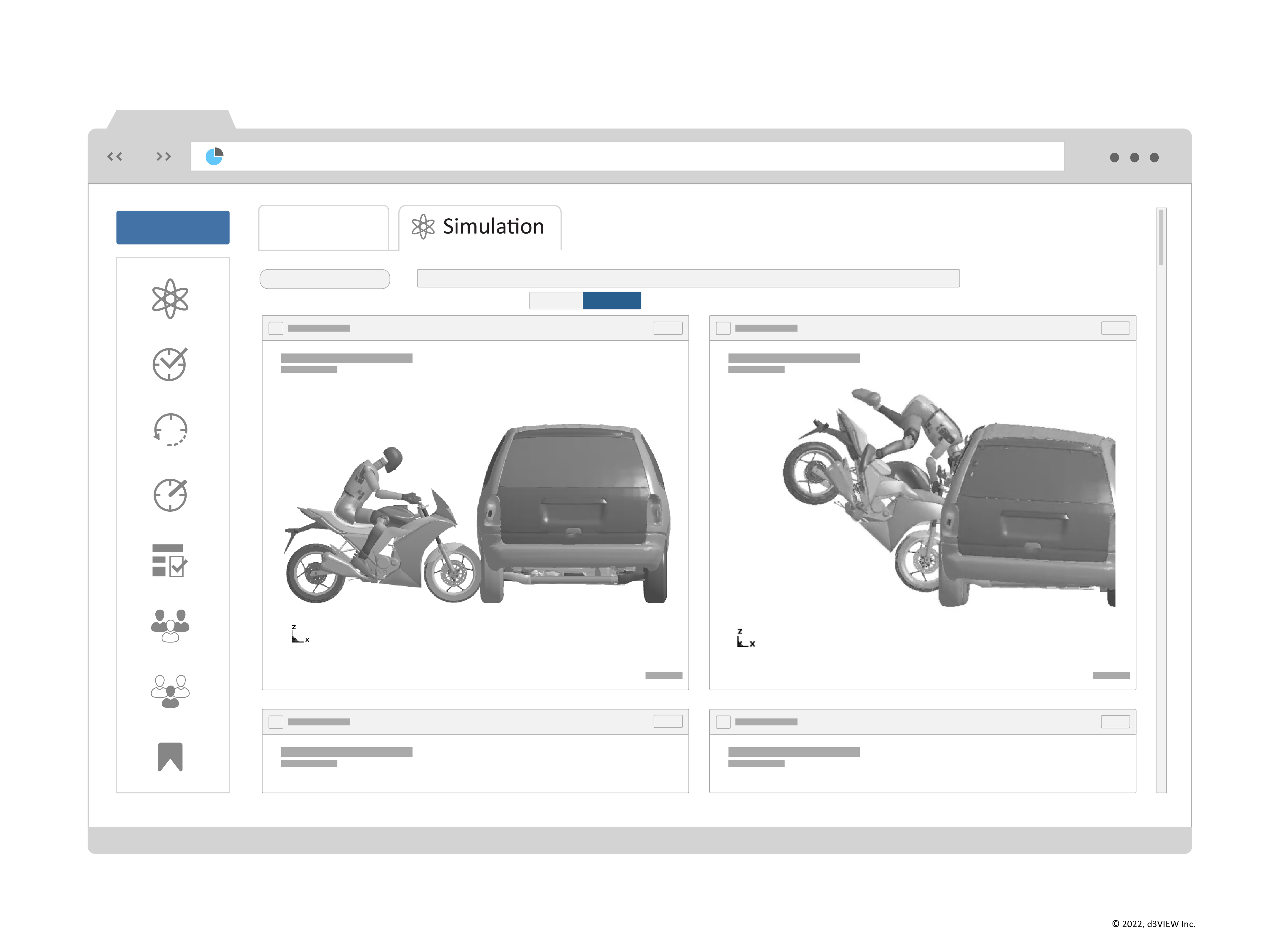
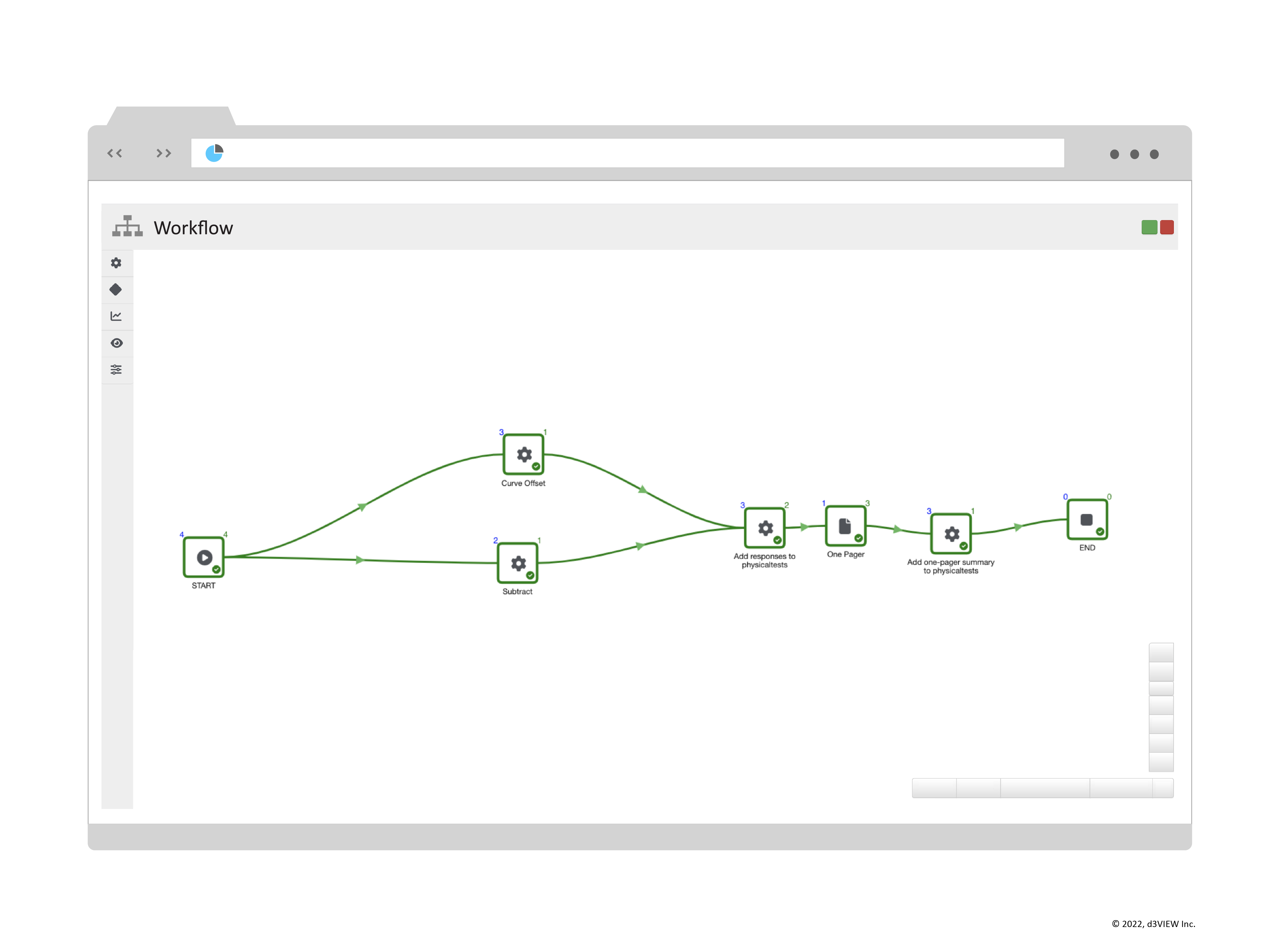
Visualizers are also connected where each visualizer can communicate with other visualizers. As an example, one visualizer can be used to highlight certain aspects of the data and this is communicated to other visualizers.
Sharing the visualizers does not mean we lose the interactivity. Sharing in d3VIEW allows full interactivity to further explore the data.