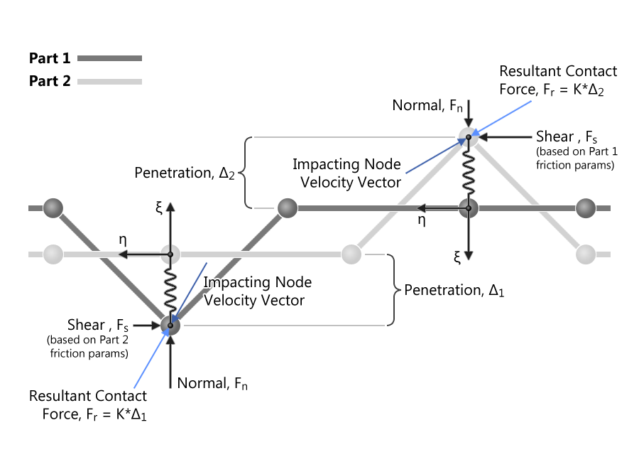
In contact-impact interactions, friction plays an important role in accurately capturing the sliding behavior. In LS-DYNA, the coulomb treatment of friction is used where a static and a dynamic friction can be defined which are used to determine the shear force while resisting penetration. By default, all contact definitions model a friction-less sliding which is a good start for initial models. The first step in activating friction in contacts is to use a non-zero static friction parameter, FS, in the *CONTACT_{OPTION} keyword. Optionally, one can define a dynamic friction, FD, which will only be used for a non-zero decay coefficient, DC. It is common to see a positive sliding energy when using non-zero friction parameters. It must be noted that non-zero friction parameters do not apply for FORCE_TRANSDUCER and TIED contacts which remain tied for the duration of the simulation. When TIED contacts are defined with failure parameters and are defined to be converted into penalty-type contacts after failure, then the non-zero friction parameters will be used to determine the shear contact forces. Figure 1 illustrates the nature of the penetration removal process when a node is detected as penetrating the closest master segment. When a penetrating node is first detected, by checking the sign of the projected normal distance to the closest master segment, a penalty force is first calculated based on the stiffness and the absolute penetration value. This force is then resolved in a local coordinate system embedded at the master element (contact point) to determine the normal and shear components. The sliding resistance is then computed using the friction parameters of the master segment and the normal force component as shown.
(Click image to enlarge)
Transitioning from Static to Dynamic Friction
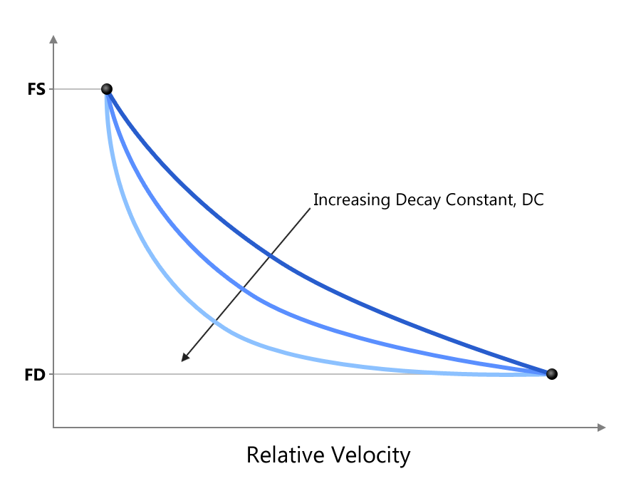
By default, LS-DYNA considers only a static value (FS). In reality, the friction is dependent on relative velocity with which the parts are sliding and this friction is usually less than the static friction value. To model this behavior, two parameters, FD and DC. The transition from static to dynamic friction is modeled using an exponentially decaying function, $latex mu = FD + (FS-FD)e^{-DC*|v_{rel}|}$, that is based on the instantaneous relative velocity of the sliding node and the corresponding master segment. The transition from static to dynamic friction is as shown below.
(Click image to enlarge)
Part Based Friction
By default, the non-zero friction parameters defined in the *CONTACT_{OPTION} keyword are used for all segments. This may be acceptable when all parts involved are composed of similar material, but it may be inaccurate when dissimilar materials are defined to interact using SINGLE_SURFACE contact definitions. In such cases, LS-DYNA provides an option to define friction parameters at the component level using the *PART_CONTACT keyword. To let LS-DYNA use the values defined at the component level, FS must be set to -1. When FS=-1, a quick look-up is done prior to computing the shear force magnitude to determine the frictional parameters using the master segment’s part definition.
Part Pair Based Friction
While the part based friction parameter definition is an improvement compared to the global values, which is applied to all parts(segments), the concept of choosing the master segment friction values can still over/under predict the sliding resistance. To illustrate this, consider two dissimilar materials such as foam (F1) and steel (S1) that interact purely by contact treatment. Using component based definitions, we can input frictional values of 0.6 and 0.2 (using FS) for the respective materials using the *PART_CONTACT keyword. Now lets consider the case of S1 sliding on F1 which will cause LS-DYNA to look up the friction parameters of the master segment (F1 in this case) to give a value of 0.6. Next consider the case of F1 sliding on S1 which will result in a friction value of 0.2. As you can see, we come up with two different frictional parameters for the same PAIR of materials interacting with each other. This is easily overcome by using the *DEFINE_FRICTION keyword available in LS-DYNA versions 970 and later. The *DEFINE_FRICTION keyword allows us to define an unlimited number of interacting part pairs and their corresponding friction parameters. When using this option, the parameter FS must to set to -2, and the parameters defined in *DEFINE_FRICTION will override all values defined using the *PART_CONTACT keyword. Now using the earlier example, lets pick a pair of F1/S1 and define an average friction value of 0.4. With this definition, when either F1 slides on S1 or S1 slides on F1, instead of looking up the part based contact parameters, LS-DYNA looks up the pair definition and uses the average value of 0.4 which provides more accurate resistance.
Graphical viewing of frictional energy
The frictional sliding energy is dissipative and can be optionally written out to binary file using the option FRCENG in *CONTROL_CONTACT which requires the parameters SPR and MPR to be set to unity along with using the command line argument “s=interface_file”. Once these options are used, LS-DYNA outputs a binary file named “interface_file” which can be viewed using LS-PrePost. Among other variables, the frictional energy is output as the component “surface energy density” which can be fringed on the contact surface.


