Attachments:
mat57_default.k
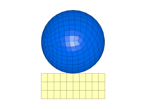
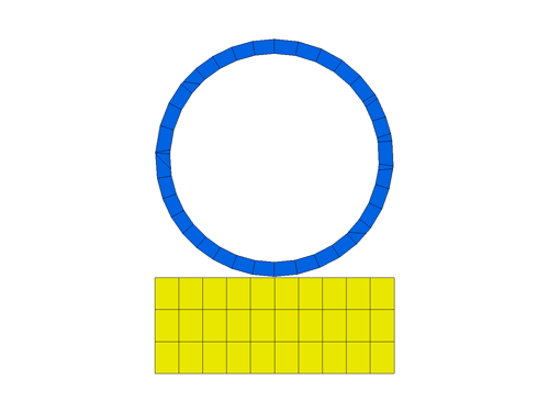
Modeling recoverable foams poses several challenges in crash worthiness as well as in low-to-medium impact velocity conditions. This is due to its relatively low stiffness when compared with structural materials which has an indirect effect on its contact-impact interactions with other materials. To review the best practices when modeling such components, we can consider a simple example of a rigid steel ball (solid elements) impacting a block of foam (solid elements). To model the interaction between the rigid block and the foam, a two-way contact such as *AUTOMATIC_SURFACE_TO_SURFACE is included. The foam is constrained using SPC definitions on the bottom face. The complete model set up is as shown in Figure 1. The recoverable low density foam is modeled using *MAT_LOW_DENSITY material model whose inputs include density, elastic-modulus, and a load curve to define its engineering stress-strain behavior for compression. The tensile behavior for this model is elastic (uses the compression Young’s modulus, E) and optionally has a cut-off stress value after which the stress remains constant in tension. Unloading behavior by default is along the loading curve but optionally we can provide some energy dissipation parameters HC and SHAPE which control both the amount of energy dissipation and the shape of the unloading curve. For simplicity, we will first ignore any hysteresis and assume that the unloading curve follows the loading curve. As mentioned before, we are going to simulation the impact using all default parameters and then we incrementally update the modeling parameters by monitoring the simulations results.
1. Default Parameters
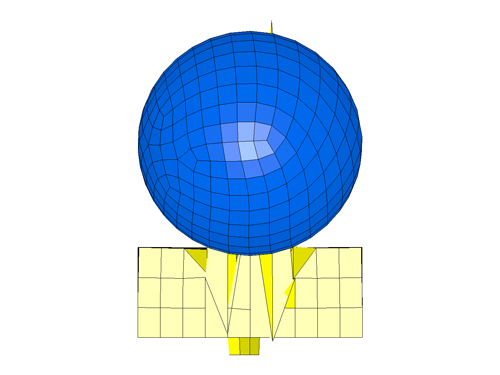
This simulation consists of all default parameters and with this definition, the job terminated abruptly with messages of ‘Negative Volume’ and ‘Complex sound speed’. The final deformed shape just prior to termination is as shown in the figure below.
Discussion — Timestep and Contact Stiffness for Foam Materials: By default, LS-DYNA computes the timestep and the contact stiffness based on the maximum value of [Young’s Modulus (E, specified in the material card), the maximum slope from the stress-strain curve (Ecurve)]. This default approach is conservative to ensure that the computed timestep is stable for all compressive strains. The default value of the modulus from this approach could either be too small (if E is greater than Ecurve) or too large (if the Ecurve is greater than E). LS-DYNA allows us to override this default logic by using a non-zero value of KCON. When KCON is non-zero, the default comparison of E and Ecurve is skipped and LS-DYNA uses KCON for the timestep and the contact stiffness calculations. In the above default simulations, the Ecurve is 10 and E is 50. Consequently, the E value of 50 was used in the timestep and contact stiffness calculations which is roughly 0.025% of the modulus of steel (200000). This huge disparity in stiffness values between the impacting bodies is naturally going to cause instabilities in contact. The alternative approach is to eliminate dependencies on elastic contacts for contact is to use a penalty contact using soft-constraint algorithm (SOFT=1 in *CONTACT). However, LS-DYNA always uses a penalty based approach based on material stiffness for contact between a rigidbody and deformable bodies. Since our ball is modeled as rigid, switching to a soft-constraint formulation will make no difference in the simulation. Therefore using KCON is recommended to alter the modulus and the recommended value is at least 1% of the modulus of the impacting material which in our case is steel. So for our next simulation, we set the KCON to 2000 which is 1% of the steel ball modulus of 200,000.
2. KCON = 2000 (1% of Steel Ball Modulus of 200000)
This simulation goes much beyond our run with default parameters but terminates due to similar messages. The final deformed shape is as shown below.
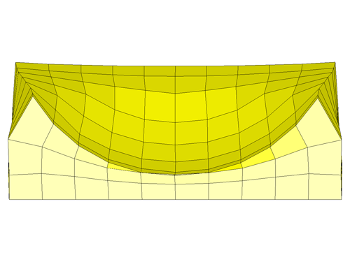
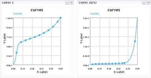
Discussion: As we can see from the cross-section image, the first row of foam elements has collapsed which would explain the negative volume issues. The reason for this is the stress determined by LS-DYNA at large compressive strains. The complete stress-strain curve is as shown below (left). As it can be seen, the last strain point is limited to around 70% but the simulation results shows the strain has reached nearly 100%. For strain magnitudes larger than the last input point in the curve, LS-DYNA extrapolates using the last slope. This may yield small stress values and fails to model the bottoming out effect that occurs at large compressive strains. The fix to this is to manually provide an exponentially increasing curve to cover compressive strains to a minimum of 95-99%. It must be noted that the manual curve must be smooth. The modified curve is as shown below (right).
3. Extended Stress-Strain Curve
This simulation worked as expected with no instability or error message and terminated normally. The final deformed shape and the transient movie is as shown below.
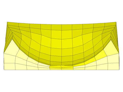
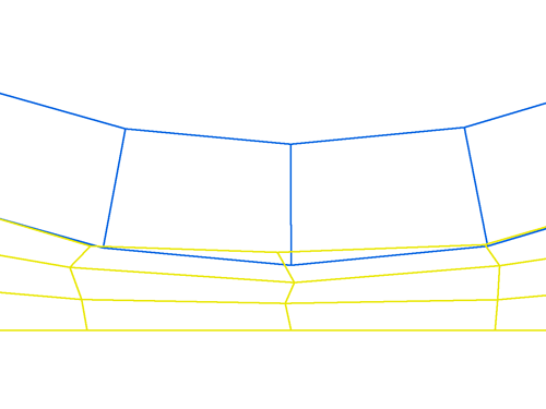
Discussion: Upon close examination of results from the run, we can find that there is some penetration between the ball and the foam block during the maximum compressive strain as shown in following figure. This is attributed to the way the segment thickness is computed for solid elements only for nodal release criteria when using AUTOMATIC type contacts. Much like the shell elements, in which the mid-surface is offset in both directions of the segment normal, the solid segments maximum allowable thickness is computed. The amount of maximum allowable thickness is based on a small percentage (5%) of the solid element diagonal which based on the element geometry could be very small. Small offset values make it vulnerable to nodal release logic used by all AUTOMATIC contacts when there is excessive penetration. For solid elements, except for type 4 and type 26 contacts) the tolerance used for determining the nodal release is 5% of the computed solid segment offset distance. The image below is a classic case of nodes being released and the fix is to increase the offset thickness. We can do this by setting SLDTHK in Optional Card ‘B’ to a value greater than 1mm to ensure no nodes are released from contact.
4. Increased Solid Element Thickness in Contact
This simulation works as expected and shows no contact penetration even for large compressive strains and meets all stability and accuracy criteria. The final deformed shape and the transient results are shown below.
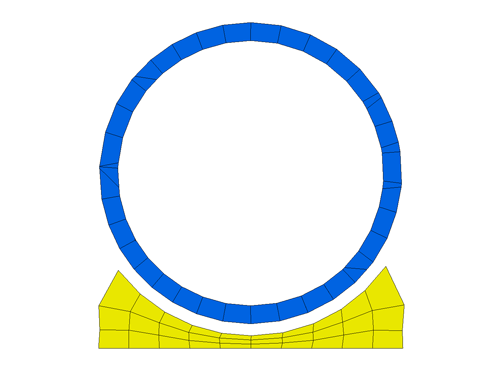
Note: What we see above is an ideal example of vertical Numerical process talked in the previous blog. The less time we spend here, the more time we would have to design.


