In many designs, parts are often press-fitted as part of an assembly which causes an initial stress condition that is important to consider in simulations. To induce initial stresses that occur in such press-fit conditions, one can either linearly/non-linearly scale the overlap (penetration) or the contact stiffness over a certain interval depending on the following choice of analysis techniques available in LS-DYNA.
Scaling of Overlap (Penetration)
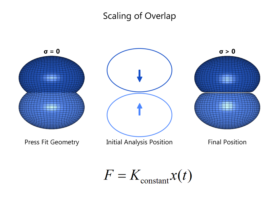
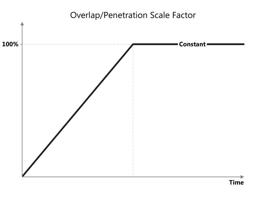
Linear/Nonlinear scaling of overlap is usually applied in transient simulations by constraining one part and moving the second part from an initial position that has 0% overlap to a final position that induces 100% overlap.This is shown in the following figure. In this method, the contact stiffness remains constant but the overlap can be thought of as being scaled over a certain interval.
Scaling of Contact Stiffness using INTERFERENCE contact
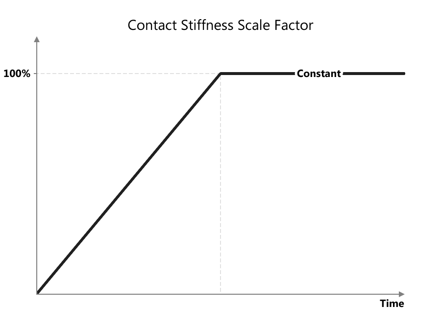
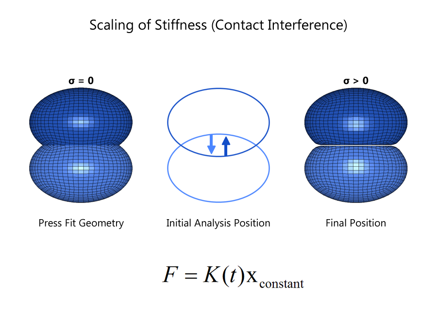
Linear scaling of the contact stiffness is employed when using the Contact Interference definitions in which the two parts are analysed where the initial geometry used in the simulation corresponds to the 100% overlap. When two parts have such intersecting volumes at time zero (initialization), non-interference contact definitions removes the overlap without the application of any contact forces which is undesirable in press-fit simulations. When using the INTERFERENCE option, LS-DYNA skips the process of removing the overlap at cycle zero but rather accomplishes the same result by removing the overlap over a user-defined number of cycles (TIME) and a user-defined contact stiffness scale factor using either or both LCID1 and LCID2 parameters that is mandatory in interference contact definitions. The resulting contact forces are applied to both slave and master components which will need to have appropriate constraints to induce the required stresses. The amount of force applied to remove the overlap is reported to the ascii file RCFORC. A sample curve for a transient simulation is as shown below where the contact stiffness scale factor is scaled linearly over the certain time interval and is held constant for the remainder of the simulation until ENDTIM is reached. The process of overlap or penetration removal can be simulated in a dynamic relaxation (LCID1) or a transient phase (LCID2). Dynamic relaxation phase can use a implicit method rather than the default explicit method using IDRFLAG in *CONTROL_DYNAMIC_RELAXATION keyword. If the press-fit is simulated in a dynamic relaxation phase, then LCID2 must be defined for the transient phase such that the contact stiffness scale factor is defined to be 100% (unity) from the start till the end of the transient simulation time.
(Click image to enlarge)
Click image to enlarge
Click image to enlarge
(Click image to enlarge)
Inclusion of Initial Stresses
Initial stresses developed from the above simulations can be stored using the INTERFACE_SPRINGBACK_LSDYNA keyword and reused using any of the following methds.
1. Reference Geometry using *INITAL_FOAM_REFERENCE_GEOMETRY keyword.
2. Initial condition using *INITIAL_STRESS/STRAIN keyword
3. Seamless continuation to a different solution following the pre-stress simulation
Notes
Since the INTERFERENCE options causes LS-DYNA to skip the segment orientation check, it is extremly important to align the shell segment normal orientations to point towards each other. There are no thickness offsets that will be considered when using INTERFERENCE option. It thickness offsets are desired, one can use the parameters SST and MST to define a non-zero thickness offset which applies for both shell and solid elements. There is a bug in LS-DYNA v971 R2 and lower versions which causes it to ignore the SST,MST parameters when the contact type is a two-way (SURFACE_TO_SURFACE). In such cases, it is recommended to define two one-way (NODES_TO_SURFACE) to achieve symmetric treatement which is equivalent to a two-way contact.
Example using Contact Interference
Here is an example of a press-fit simulation in which the foam is defined as the master and the rigid as a slave in a CONTACT_NODES_TO_SURFACE_INTERFERENCE definition. To avoid any movement of the rigid block, it is prescribed to to have zero displacements until 100% overlap is removed at 0.01seconds. After the overlap is eliminated, the pre-stressed foam is further compressed by moving in the z-direction. The stiffness scaling curve is defined using a DEFINE_CURVE_FUNCTION.
*CONTACT_NODES_TO_SURFACE_INTERFERENCE_TITLE
1, interference
6, 4, 3, 3,
0
,, 4.0, 4.0
0, 212
*DEFINE_CURVE_FUNCTION
212,
$ power of 2
MIN( POW(TIME,2)*10000, 1.0 )
$ linear
$MIN( TIME*100.0, 1.0 )


