A few questions recently from some users while teaching a class prompted me to write this overview regarding the data output, particularly for shell elements, into D3PLOT and how the post-processors plot them. The brief overview is listed in the form of list items for a quick read.
1. Element output are always element centered and is in global system unless specified using CMPFLG in *DATABASE_EXTENT_BINARY. Element centered data such as strain and stress tensor are output for each element’s integration point both in-plane and out-of-plane. Strains are not included by default and must be turned on using STRFLG in *DATABASE_EXTENT_BINARY. Additionally, only 3 layers are written by default in the fiber or normal direction and can be user-defined using the value MAXINT parameter in *DATABASE_EXTENT_BINARY keyword. For more information you can see the other post here.
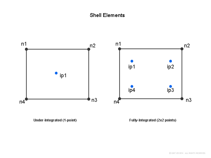
2. Under-integration element has just one in-plane point output while S/R element such as type 16 has 2×2 in-plane points. These two are shown below.
(Click to Enlarge)
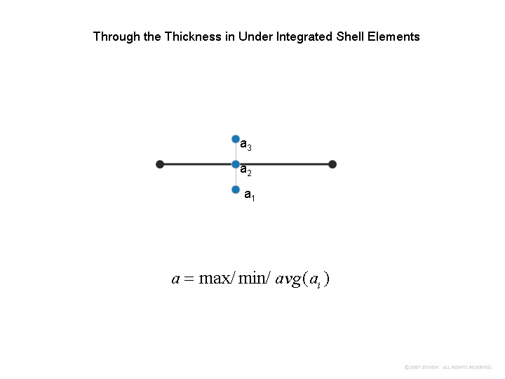
Additionally, each integration point in the fiber direction is also output based on the value of MAXINT as shown below. When multiple layers of data is output, it is common for the post-processors to allows users to take either the maximum, minimum or the average value among them. LS-PREPOST defaults to the maximum value among all the layers.
3. By default, many post-processors provide options to fringe these time history element centered data. In order to fringe, they compute the Nodal Values that is computed as follows. For both one-point integration and 2×2 in-plane point elements, the average, min or max data is first computed for each in-plane integration point as show below.
(Click to Enlarge)
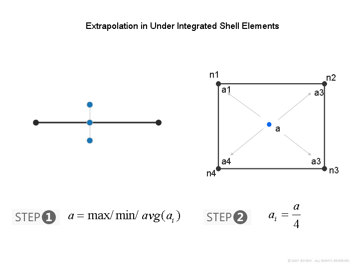
Now once this value is computed, depending on the type of element formulation, the nodal values are computed. For under-integrated element, the nodal values are simply 0.25 of the value computed from above. This is shown below.
(Click to Enlarge)
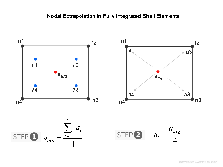
For the 2×2 in-plane point element, after computing the average, min or max value from the fiber direction integration points, the average of the four in-plane points are then obtained as shown below.
(Click to Enlarge)
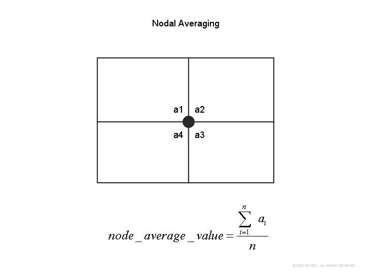
The nodal values are then computed by taking the average value from each element as shown below irrespective of the type of element.
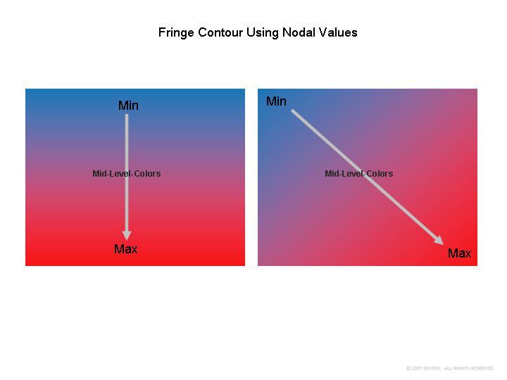
4. Fringing is then performed by contouring a color range that goes from a color value associated with MIN (usually blue) and ends with a color value associated with MAX (usually red) as shown below.
(Click to Enlarge)
Conclusions
It is clear that the nodal values will be less than the element integration point values if the stress or strain gradient is not smooth. Looking at nodal values contour may be a start but for detailed analysis, the element value must be viewed to better understand the stress or the strain data.


